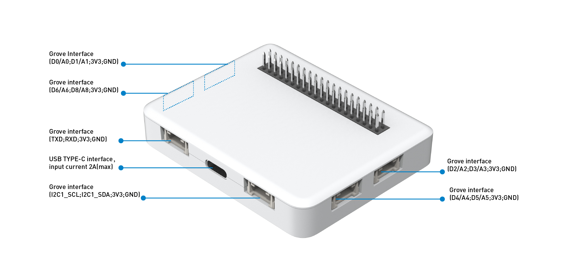
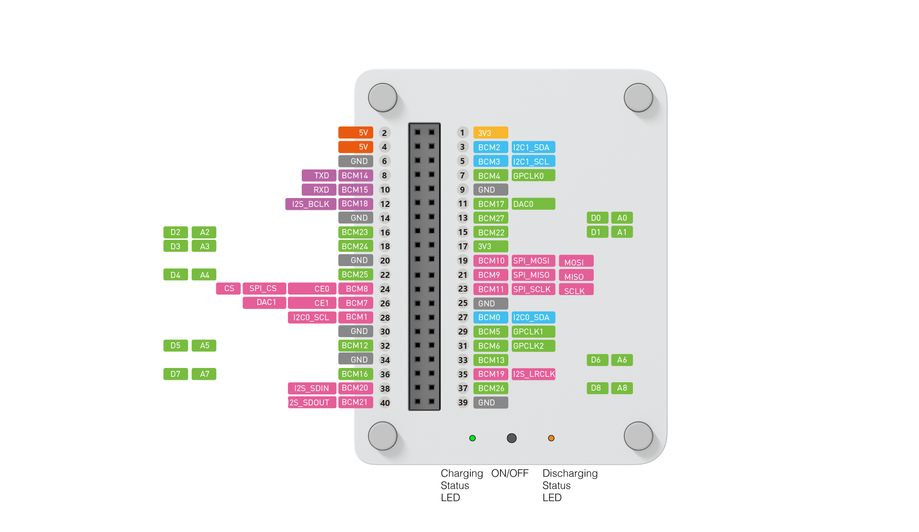
The Wio Terminal Battery Chassis is a must-have extension board for Wio-Terminal Dev Board as it provides an external power source for Wio Terminal to enhance its portability and compactness. It has a 650mAH rechargeable lithium polymer battery, battery charging/discharging status LED, 4 Grove Analog/Digital Ports, 1 Grove I2C Port, and 1 Grove UART Port, as well as the ABS enclosure for aesthetic and protection. There is also the same Raspberry Pi 40-pin compatible GPIO at the back of the Wio Terminal Battery Chassis for more add-ons!
With Wio-Terminal Dev Board + Wio Terminal Battery Chassis, you are able to build the most powerful and compact IoT projects with no ease.
The new version battery board built-in BQ27441-G1A fuel gauge for LiPo batteries.

What is Grove?
No jumpers or soldering are required, Grove makes it easier to connect, experiment, and simplify the prototyping process significantly. We have developed more than 300 Grove modules, covering a wide range of applications that can fulfill a variety of needs. Each one comes with clear documentation and demo code to help you get started quickly. Not only are these open hardware, but we also have open-source software.
Documentation
Wio Terminal Chassis Battery WIKIHighlighted Features
- Built-in 650mAh Rechargeable Lithium Polymer Battery
- Battery charging/discharging status LED
- Battery On/OFF Button
- Built-in BQ27441-G1A fuel gauge for LiPo batteries
- USB Type-C Charging
- Overcurrent protection
- Hiccup mode/Hiccup Protection
- 4 x Grove Analog/Digital Port
- 1 x Grove I2C Port
- 1 x Grove UART Port
- Magnets are hidden inside the enclosure so that it can be stuck on the Whiteboard!
Pinout Diagram


Specifications
- The Wio Terminal Battery Chassis is either powered by a USB Type-C interface or the internal battery. The maximum input current of USB Type-C is 2A, and the input voltage range is 4.75V ~ 5.25V.
- The built-in battery is a rechargeable lithium-polymer battery, with a capacity of 650mAh. The battery output voltage is 3.7V, with a battery charging voltage of 4.2V.
- The maximum current allowed by the board is 660mA. If the board is on the charging status then the green LED turns on.
- When the battery is on low battery, the battery board will enter the trickle charging status and the current of the trickle charging status is 30mA.
- The battery board can output a 5.15V to 40Pin female interface with a maximum current of 380mA.
- The Wio Terminal Battery Chassis standby current is less than 200uA.
- The battery board mode can switch by pressing the mode button, and then the mode is determined by the LED color:
- Green LED: Light On is mean the board charing.
- Red LED: Light on is mean the OTG(battery discharge) enable.
- Yellow LED: Light on is mean the male interface output/input 5V.
-
When the Type-C is unplugged, the board uses the battery to power the Wio terminal by default. If plug the type-C the battery board will automatically force into the battery charging state(Green light on) until the battery is full, but you are able to press the mode button to control the battery board and shift to default mode.
-
The battery board can be charged by the 40Pin female interface, meanwhile, the Yellow and the green LED will light up until the green light is off when the battery is fully charged.
-
The battery board can read charging information via an I2C port on 40Pin female interfaces, such as charging status, battery voltage, average current, remaining capacity, full capacity, average power, and health status.
Precautions
- The Wio Terminal Battery Chassis cannot output 3.3V voltage by itself, it can only output 5V voltage.
- When the Wio Terminal Battery Chassis is switched from battery charging mode to battery power mode, there will be a 500 ms voltage drop time.
-
The battery can only be charged by the I2C on a 40Pin female interface or USB Type-C.
-
When the input voltage falls below 4.3V, the USB Type-C or 40 female pin header will stop charging, but the green light will keep on.
-
If the battery voltage is below 3V in OTG(battery discharge) state, the battery board will stop the discharge and the red light off.
-
When the battery board is on the OTG mode, If The output is shorted, the mode will automatically switch to hiccup mode until the short circuit is repaired, and then the board recovers to normal power supply mode.
-
If the battery is removed while the board is in charge mode, the board will switch to failure mode, and the green light blinks at a frequency of 1Hz.
-
When the battery board is not in use, please press the button to enter sleep mode and all the LEDs will off.


